Clock Domain Crossing: Constraints-Based Sign-Off Methodology
By Sharan Mohan, Pinkesh Shah, & Rambabu Singampalli
Western Digital
I. Case Study Executive Overview
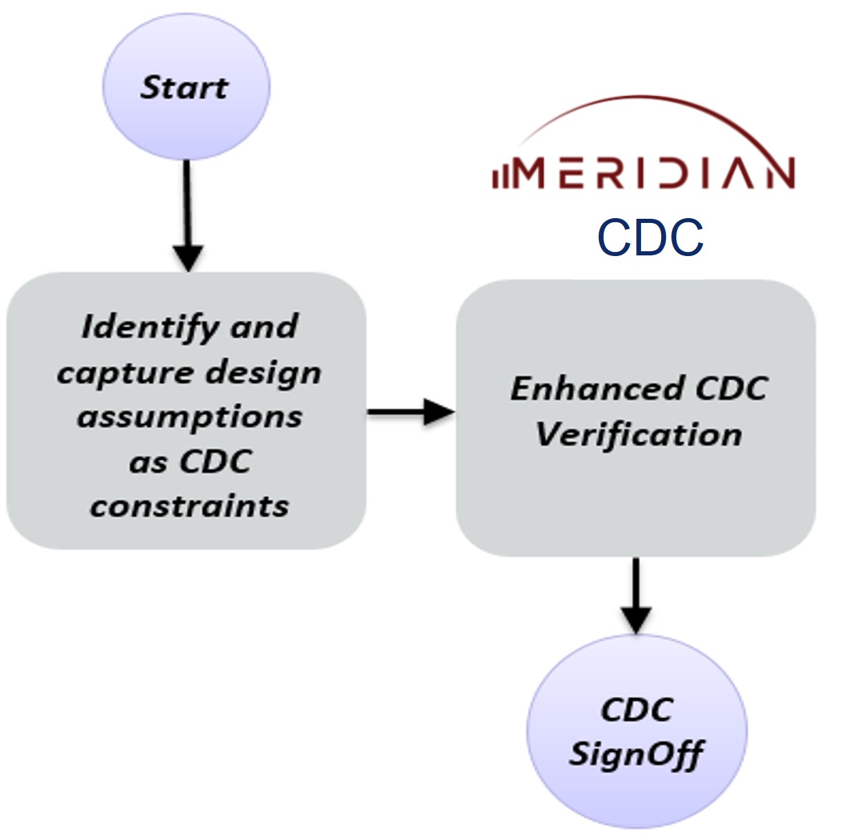
This case study covers Western Digital’s enhanced constraint-driven clock domain crossing (CDC) sign-off methodology with Real Intent Meridian CDC, as presented at the 2021 Design Automation Conference.
Western Digital’s enhanced methodology achieved a two-thirds to a three-quarters reduction in total CDC sign-off time, achieving sign-off in only two weeks, compared with a typical six to eight weeks.
II. Problem Statement & Goal
ASIC respins are expensive in terms of cost and delivery impact — good specifications, randomized simulations, and thorough verification are critical.
Functional and clocking issues rank highest among bug escapes sources; clock domain crossing issues are typically a mix of clocking and functional bugs. System on chips (SoCs) have multiple asynchronous clock domains with complex interactions; additionally, they contain several IPs from third parties, each with different configurations.
Given this complexity level, a waiver-based methodology to clean up CDC violations can be risky and lead to silicon failures.
Goal: Western Digital’s goal was to implement an accurate, correct-by-construction clock domain crossing sign-off methodology for its SoCs while reducing its engineering effort.
III. Clock Domain Crossing Verification Challenges
Clock domain crossing verification challenges for deep submicron designs are related to:
- CDC handshake protocols. Western Digital designers must identify the paths that are not instantiating the correct CDC handshake structures. Real Intent Meridian CDC sign-off tool ensures this.
- Design and architectural assumptions. The designer’s assumptions must be incorporated into the CDC methodology. This is commonly done through waivers, however, this approach may lead to a large number of waivers, some of which may be incorrect when integrating different blocks. The result is that actual bugs may be masked in the design.
This clock distribution block diagram shows what a typical clock distribution would look like in an SoC.
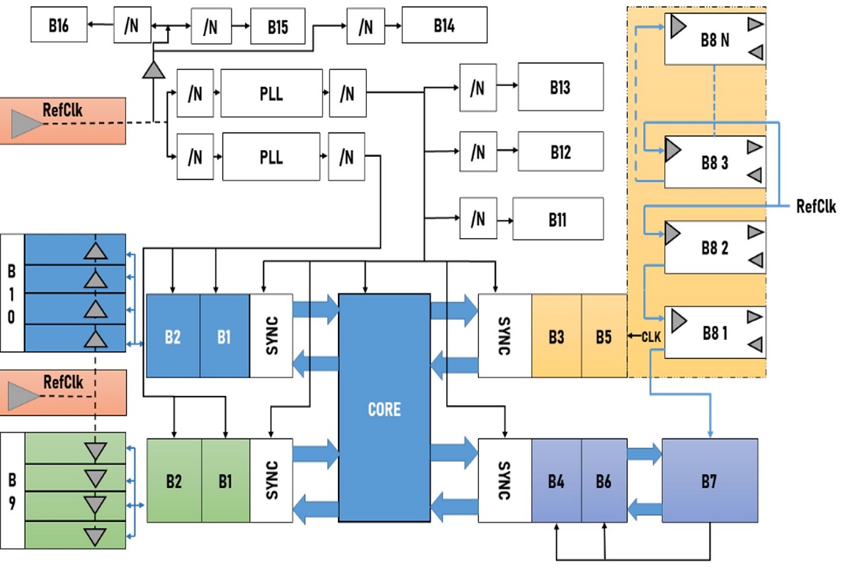
Clock Distribution
As clock distribution limits are tested, previous second-order issues — such as clock jitter in data and control transfers — increase in importance. This means that even crossings across synchronous clock domains that were previously deemed safe must also be carefully designed and comprehensively verified.
IV. Reset Verification Challenges
Reset Architectures in SoCs
Today’s SoCs integrate numerous IP blocks from different third-party providers, each with a reset implementation. As a result, the associated bugs cannot be captured through conventional STA or CDC design verification tools.
Such complex reset architectures need a dedicated solution to identify and contain critical domain crossing bugs. [Real Intent Meridian RDC addresses this specialized need, but was not covered in this presentation]
This reset distribution block diagram shows how resets can be distributed in an SoC. The bulk of the core logic is tied to a system reset signal, and each third-party IP block has a reset (“B_reset”).
The system reset signal resets the entire controller, including the third-party IP blocks.
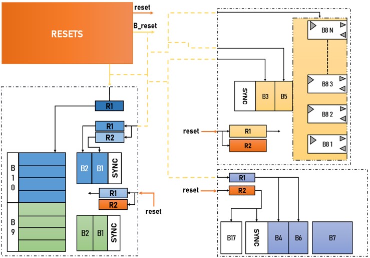
Reset Distribution
Ensuring that all the reset sources propagate safely to the intended destinations under all conditions is a significant challenge. Additionally, because soft third-party IPs have reset synchronizers, they must also ensure reset domains do not cross data paths.
Reset Verification Challenges
This example shows a case where a flop in the design received an asynchronous reset generated from an asynchronous clock domain. This can cause undesired behavior during reset removal.

To ensure a reset register will not have metastability, the reset de-assertion logic should not align with a clock-edge, or the clock must be turned off when the reset is de-asserted.

To protect downstream logic from these resets, designers must add a suitable reset synchronizer.
V. Synchronizer Verification Challenge
With the inherent CDC sign-off challenges, there is also a need to have complete and intended constraints; this is because an incorrect assumption can result in missing CDC violations and potential silicon failure.
The following example shows a case of a missing synchronizer that wasn’t reported due to an incorrect clock relation constraint. The error was not caught in the later stage of the ASIC flow during dynamic timing simulation.
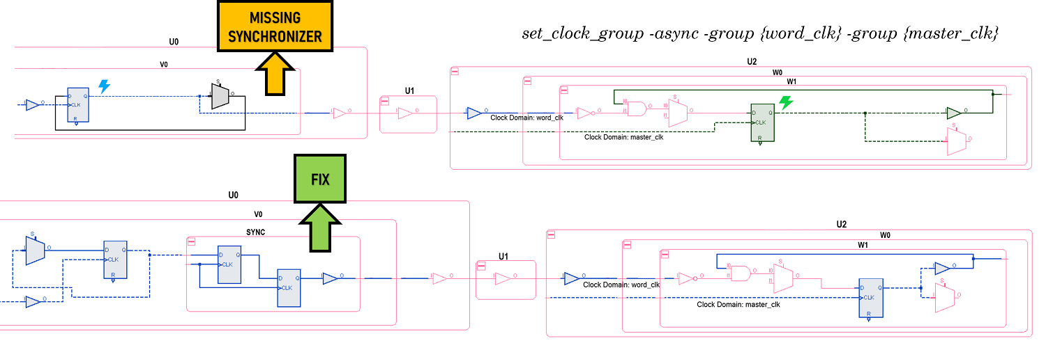
A set_clock_group is a relevant constraint for assigning the correct clock relationship in a design.
VI. Constraint-based CDC Methodology
Western Digital proactively added the following types of constraints to its sign-off methodology, which Real Intent Meridian CDC supports.
- Mutex constraints – for signals which cannot toggle at the same time
- Static constraints – for SRAM configs and SFR registers which are stable and don’t change during functional operations
- Ignore paths constraints – for CDC paths synchronized using sideband signals
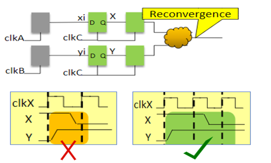
Mutex constraint for unrelated signals
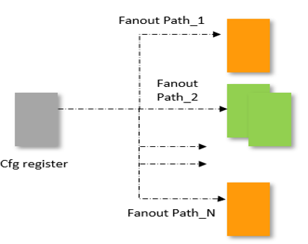
Static constraint for configuration registers
Real Intent can extend the methodology to convert constraints into System Verilog assertions to verify the assumptions or conditions. These can be functionally verified using any commercial simulator. For purposes of this presentation, it was assumed the constraints were correct, so this step was skipped.
VII. Clock Domain Crossing Constraint Types
The mutex, stable and ignore paths constraints covered below impact multiple types of violations in a single run, reducing the overall violation count for a lower noise report.
A. Mutex Cases
In this Mutex case example, the designer sets a list of mutually exclusive signals. The specified signals in the design cannot transition together.
- If all the signals reported in a violation cannot transition together, they can all be specified using the mutex constraint.
- If only a few signals out of all the signals reported in a violation cannot transition together, only those signals that cannot transition together should be specified using the mutex constraint.
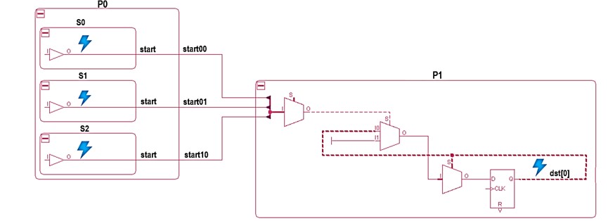
This impacts violations where:
- Multiple asynchronous signals combine and feed a synchronizer.
- Synchronizers fed by combinatorial logic are driven by asynchronous signals from one or more other domains – synchronizers with glitch potential.
- Groups of control signals re-converge in the receiving domain.
The mutex constraint moves these types of violations to a tool-waived category.
B. Stable Cases
The designer can add a stable value constraint to the net “config0” in the example schematic. This will make the net’s value unchangeable from the very first value it gets; for instance, if the net gets assigned a low value, it will remain low during the entire analysis.

This net is now assumed to be stable and will be excluded from the clock domain crossing analysis. The value of 0 or 1 will be propagated to its fanout, allowing its fanout and potential crossings driven by it to be verified.
C. Ignore Paths Cases
In the example schematic below, the designer adds an ignore paths constraint to “wr_data[0]”. It is synchronized by a sideband signal and is considered multi-cycle.

The CDC analysis will then ignore the specified path; no violations on these paths will be reported, even though they may exist.
They can add ignore paths constraint for static or debug flops so that the CDC sign-off analysis will also ignore those flops.
VIII. Results: Constraint-Based Clock Domain Crossing Sign-Off
Western Digital’s enhanced constraints-based CDC sign-off methodology allowed us to
- Catch real issues related to unsafe CDC handshake interfaces. (Waivers are typically not used for handshakes.)
- Capture design assumptions in the form of easily reviewable and verifiable constraints.
- Reduce the CDC verification and sign-off debug effort.
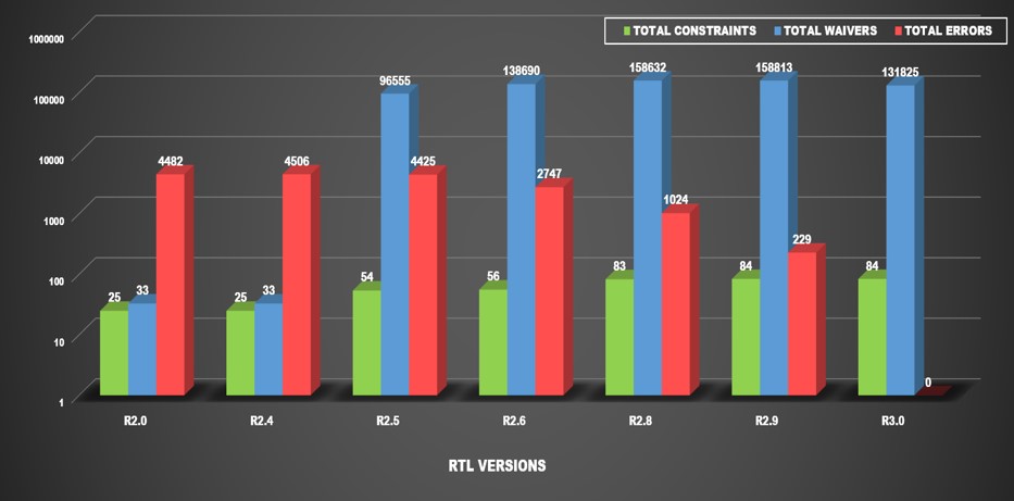
The Western Digital design referenced below has 42 million gates and 66 clock domains.
The graph plot below shows constraint variations in green, waivers in blue, and errors in red for each of the RTL versions. RTL version R2.0 is the initial release, and R3.0 is the final release.
As you can see from the data, capturing design assumptions in the form of constraints:
- Reduced the number of errors across each new RTL release.
- Made for easier reviewability and verifiability. Only 84 total constraints were applied to clean all the errors in R3.0 using a constraints-based approach. In contrast, a waiver-based approach would require applying over 130 thousand waivers.
Using a constraints-based methodology helped reduce debug effort in CDC verification. Cleaning up violations using waivers is a lengthy, iterative process; additionally, waivers may become obsolete as the design progresses.
The conclusion below includes Western Digital’s overall time savings.
IX. Conclusion: CDC Sign-Off with 67% to 75% Time Reduction
Western Digital was able to complete its clock domain crossing sign-off in under 14 days with its enhanced constraints-based methodology, including time setting up the constraints; in contrast, a waiver-based approach usually took approximately one and a half to two months to complete CDC sign-off.
SoCs have complex clock interactions across IPs and FIFO interfaces – the interaction is a critical source of CDC verification complexity.
The two graphs below show the reduction in effort versus the time for both the waiver-based and constraint-based approaches. This includes the estimated time it would typically take a designer to set up the constraints and waivers, along with the time required for debugging the violations.
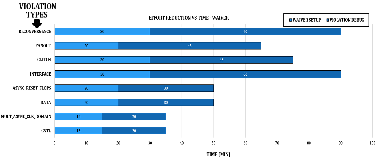
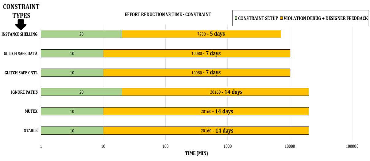
Since a handful of constraints can impact multiple violations, as shown in this table, the time taken to sign off using a constraints-based methodology is a lot less when compared to waivers.

Western Digital’s enhanced constraints-based CDC methodology reduces noise and debug effort compared with applying for waivers. It also made the CDC tool aware of reset and clock architecture assumptions. Finally, it verifies their designer assumptions through both dynamic and formal means.

